-
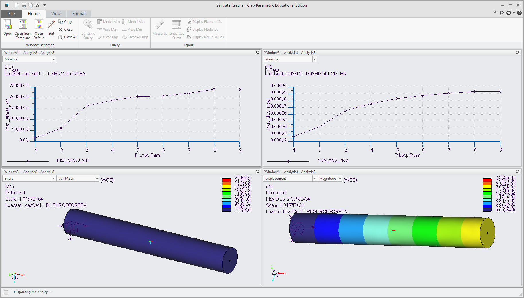
Ran FEA(Finite Element Analysis) on Pushrod with CAD software, Creo Parametric. Created the plots for the maximum von mises stress and the maximum displacement. Click here for an enlarged view.
-
Recorded video of an airfoil at a low angle of attack in a circuit water channel I set up with my lab team, in order to observe the flow around the airfoil using colored dye markers. In the video you can see vortex shedding.
-
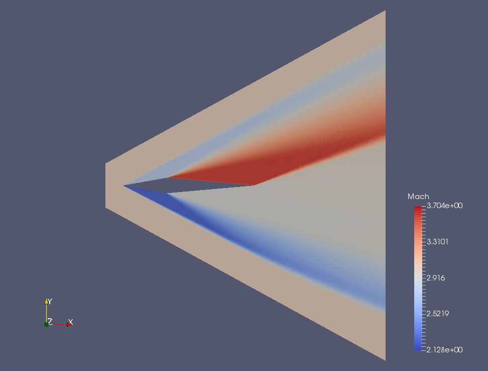
Developed a Mach number field around this airfoil using Paraview. Click here for an enlarged view.
-
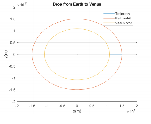
Developed a trajectory from Earth's orbit to the orbit of Venus in Matlab. Click here for an enlarged view.
-
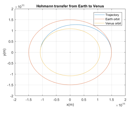
Developed a Hohmann Transfer from Earth's orbit to the orbit of Venus in Matlab. Click here for an enlarged view.
-
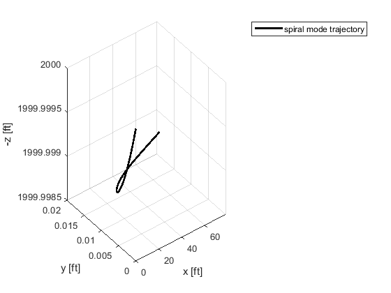
Developed the spiral mode for an aircraft in Matlab. Click here for an enlarged view.
-
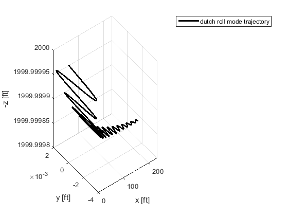
Developed the Dutch Roll Mode for an aircraft in Matlab. Click here for an enlarged view.
-
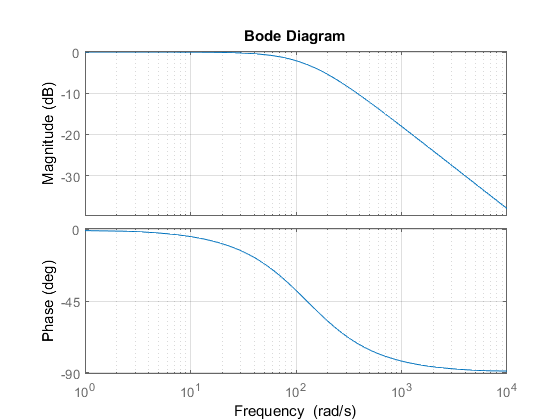
This is a graph of the frequency response of a Resistor Capacitor circuit system, I plotted it in Matlab. Click here for an enlarged view.
-
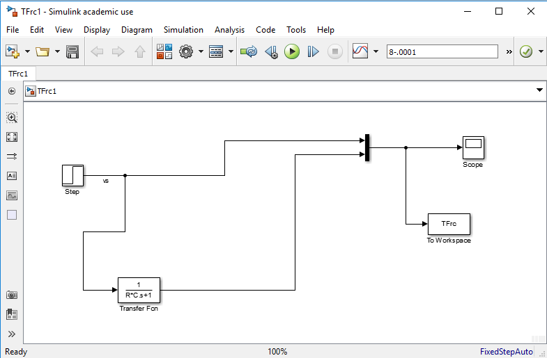
This is a block diagram for the transfer function of a Resistor Capacitor Circuit system, I made it in Simulink. Click here for an enlarged view.
-
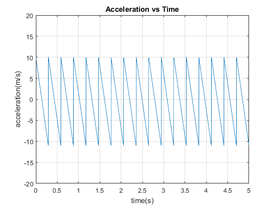
This is a plot of the acceleration an Accelerometer I calibrated, experienced versus time, I plotted it in Matlab. Click here for an enlarged view.
-
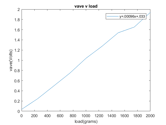
This is a plot of the average Voltage of a Load Cell I calibrated, experienced versus the load, I plotted it in Matlab. Click here for an enlarged view.
-
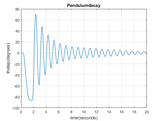
This is a graph of the angles a pendulum was at over time as a Motor Pendulum was swaying, I plotted it in Matlab. Click here for an enlarged view.
-
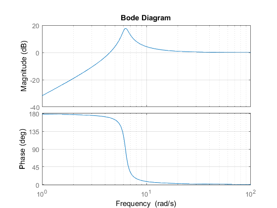
This is a graph of the frequency response of a Motor Pendulum, I plotted it in Matlab. Click here for an enlarged view.